Sega Master System II Composite Mod
PROJECT:
15
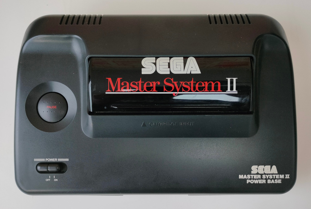
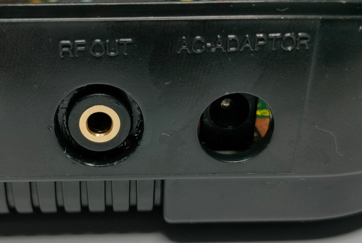
The Sega Master System II is simply a cost reduced version of the original Master System console. Part of the cost reduction was removing the composite video port, leaving only an RF video connection. Apart from RF video being inferior to composite video; in 2012 the UK turned off their analogue TV service which resulted in many new TV's being shipped without an analogue RF tuner. Available off eBay, this simple module replaces the RF module on the SMS II and supplies standard composite video and audio signals.
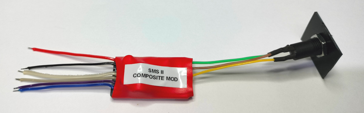
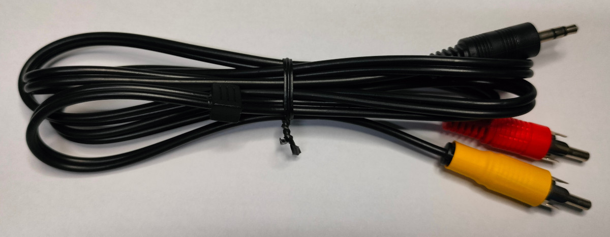
This mod kit includes a composite mod PCB, pre-wired with output socket and connection wires and a composite video cable with phono video and audio connectors. All that is required is some screwdrivers, soldering iron, de-soldering tool and some glue. This mod is of moderate difficulty and requires good soldering skills.
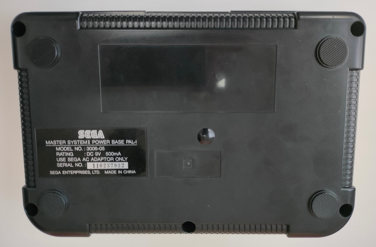
Fitting Instructions Step 1: Remove the 5 screws from the underside of the SMS to remove the top of the console.
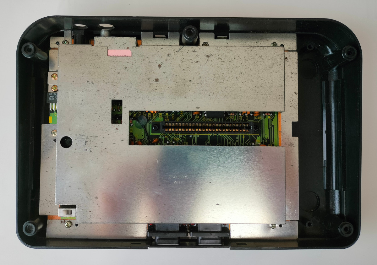
Step 2: With the top removed it will expose the metal shield. Remove all 8 screws around the edge of the metal shield and then remove the top of the shield. With the top of the shield removed it should be possible to remove the SMS printed circuit board (PCB) from the lower shield and bottom plastic.
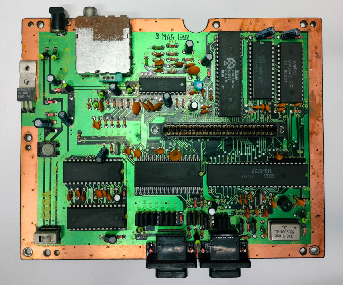
Step 3: The RF Modulator will need to be completely removed from the PCB. Looking at the PCB with the 2 controller ports at the bottom, the RF Modulator should be located to the top left next to the power socket. The RF Modulator is a square metal component with the RF video out socket to the top left. To remove this de-solder the 3 metal tabs and the 3 connection pins on the underside of the PCB. The 3 metal tabs are sometimes twisted to retain the RF Modulator and will need straightening out before they will release the RF Modulator. The RF Modulator can usually be carefully prized out of the PCB with a flat bladed screwdriver.
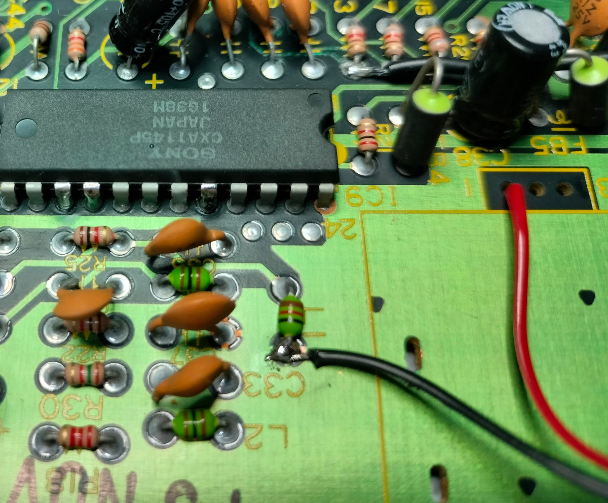
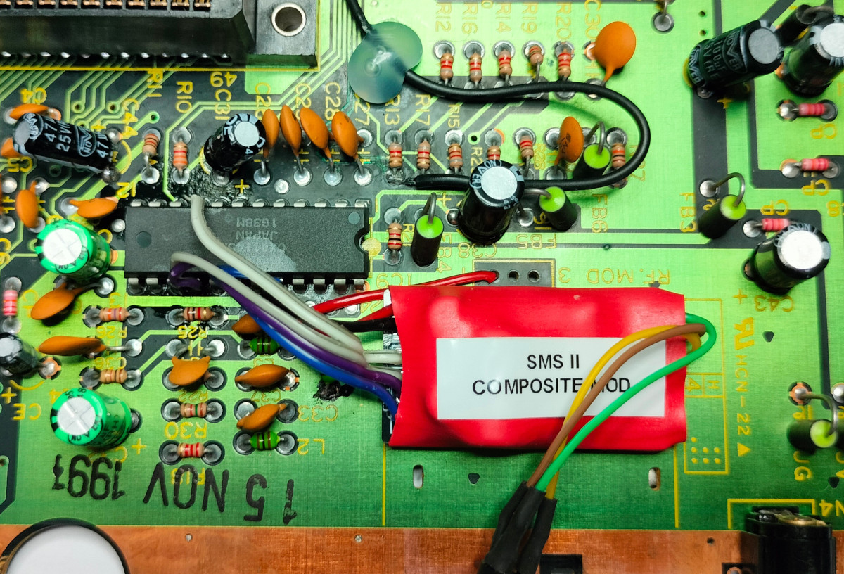
Step 4: The red and black on the composite mod circuit need to be soldered to VCC and GND on the SMS PCB Respectively. GND (black wire) can be found in many places on the PCB including and component leg connected to the ground plane or or pin 24 of the CXA1145. VCC (red wire) can also be found in multiple places such pin 1 of the RF Modulator connection points or pin 12 of the CXA1145.
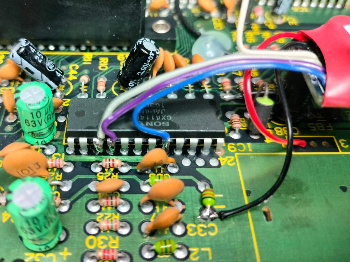
Step 5: Locate the CX1145 I.C. on the SMS PCB. On many revisions of PCB this is identified as IC9 and is located near to where the RF Modulator was. Solder the 4 wires (white, grey, purple & blue) from the composite mod circuit to the following pins on the CX1145 I.C.;
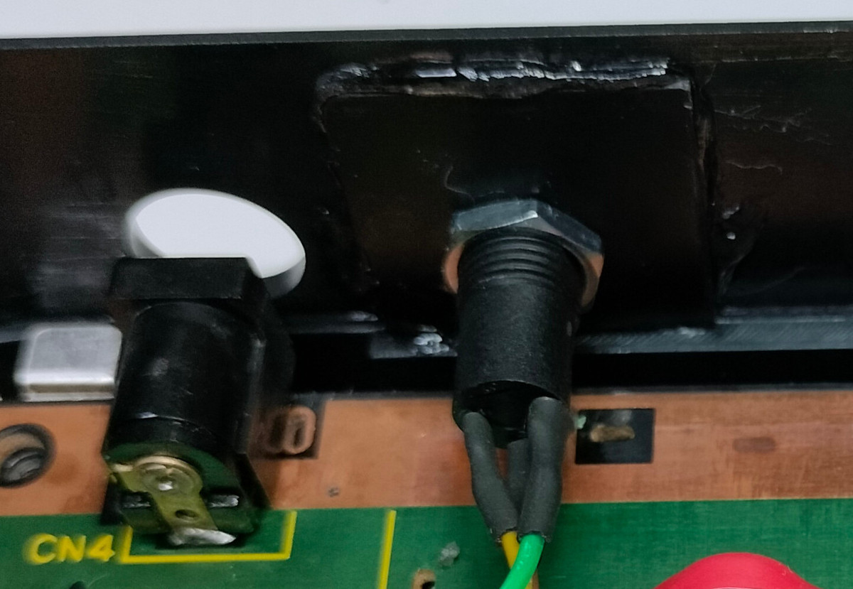
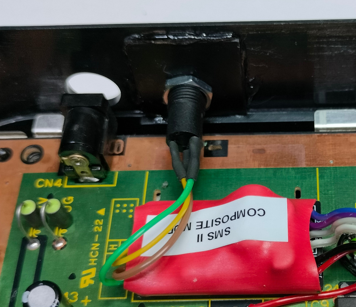
Step 6: With the composite mod circuit all wired in it's probably a good time to test it. Plug the supplied composite video cable into the socket on the composite mod circuit and in to a suitable TV. Connect up the SMS PCB with power and a game in the cartridge slot (if your model has no built-in game), turn it on and check there is a good video picture and sound. Make sure the test is quick before the regulator gets too hot as it is currently not screwed down to the heatsink. Step 7: If it's all good re-assemble the SMS PCB into the lower part of the metal shield and then back into the lower part of the plastic case. Step 8: Using a suitable glue fix the new video connector into the hole in the plastic case where the RF video port used to be. I recommend either a hard plastic glue or a super-glue gel. Normal super-glue can be used but it's tricky to stop it running all over the video socket and causing damage.
Step 9: Using the attached sticky pad, secure the composite mod circuit to the SMS PCB. An ideal place is where the RF Modulator was originally located.
Step 10: Once the glue on the video connector has fully dried (best left overnight) reassemble the SMS console, which is the reverse order of steps 1 & 2. Enjoy your modified console.
|